Air-cooled compute or communications
A one- or two-sided vapor arrangement could spread heat to external fins, with natural or forced airflow selected for the actual load and environment.
Cooling designs
Direct liquid, sealed vapor chambers, or a combination: ColdBoard can be explored with different cooling arrangements on each board face. The concepts below show how the same circuit-bearing architecture could support a range of products.
ONE ARCHITECTURE / MULTIPLE CONFIGURATIONS
The PCB can carry circuitry and thermal paths while also forming a chamber wall. Select the arrangement for each face, then define how heat leaves the complete product.
Choose a lower flow region beneath exposed electronics, or flow around both populated faces.
Pumped flow through the moduleExplore direct contact → 02 / VAPOR ONLYUse a chamber below an exposed-top board, or a separate chamber on each populated face.
Heat exits through the housingExplore vapor chambers → 03 / HYBRIDA sealed upper vapor region combines with direct liquid cooling underneath.
Different boundaries on each faceExplore the hybrid →Proposed design families for evaluation and licensing. Chamber geometry, materials and operating limits are application-specific.
01 / DIRECT DIELECTRIC CONTACT
Cool the underside while the top stays exposed, or surround both populated faces with dielectric liquid.
The board spans the module and seals against its surrounding frame. In the single-sided arrangement it forms the roof of the lower liquid region, with heat routed from exposed top-side electronics through selected board paths. In the double-sided arrangement, dielectric fluid contacts the upper and lower components and wetted board surfaces directly.
Switches every 3 seconds · Select a tab to hold a view.
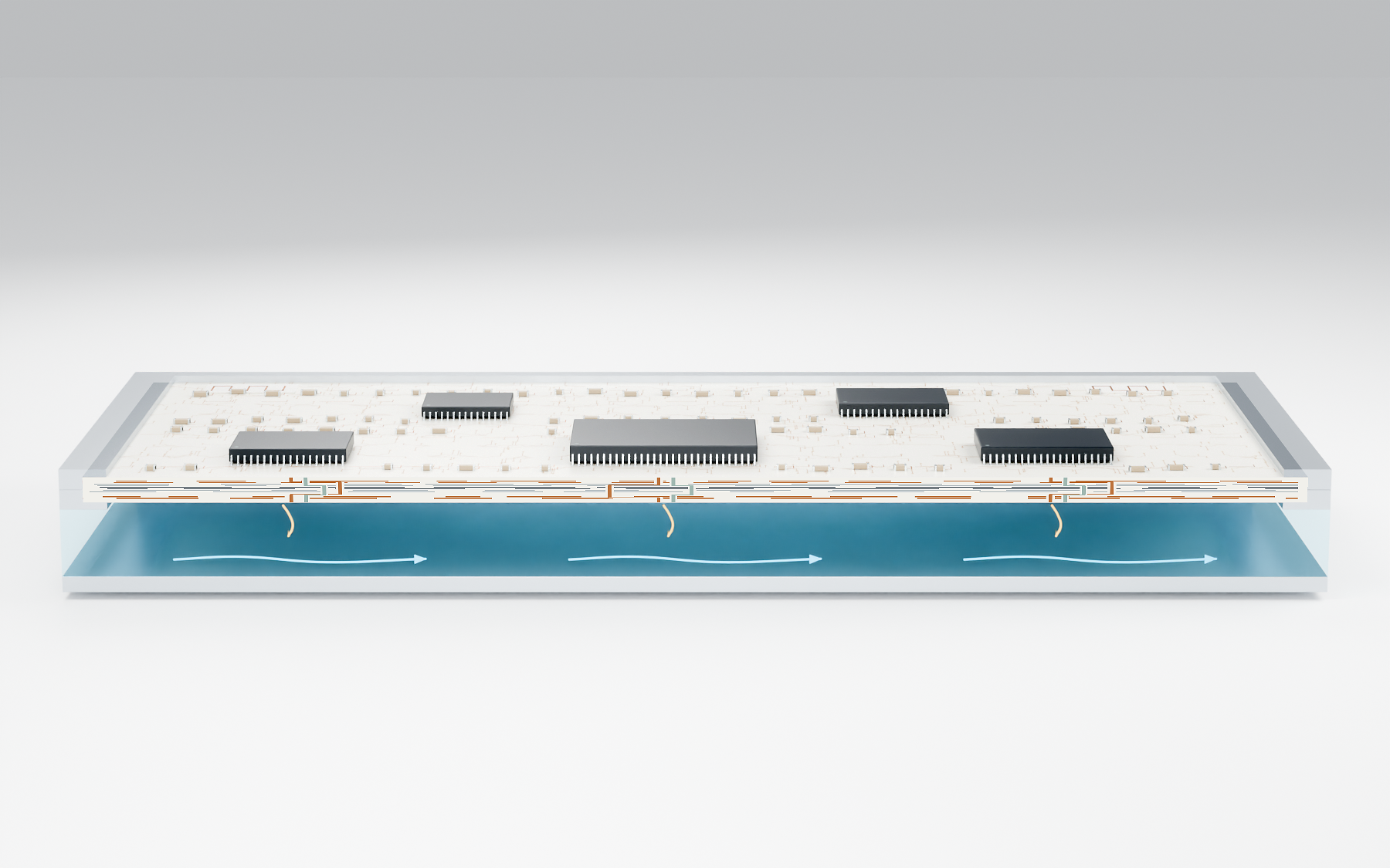
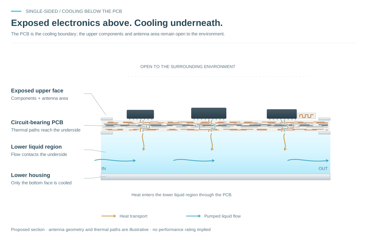
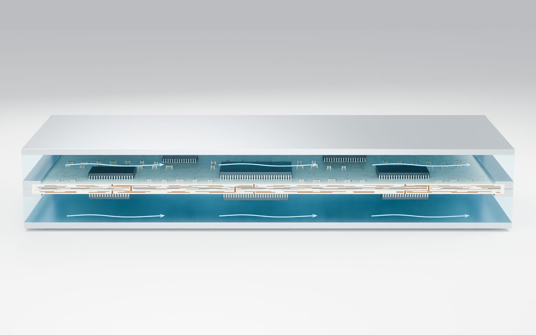
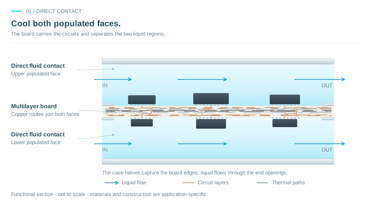
Qualify the dielectric fluid and every wetted component, joint, coating and insulation system.
Distribute flow across the active area and manage pressure loss, bypass and local stagnation.
Design the board, frame, seals and fluid connections for the pressure and service requirements.
02 / VAPOR-ONLY OPTIONS
Use one sealed chamber below an exposed-top board, or place a chamber on each populated face.
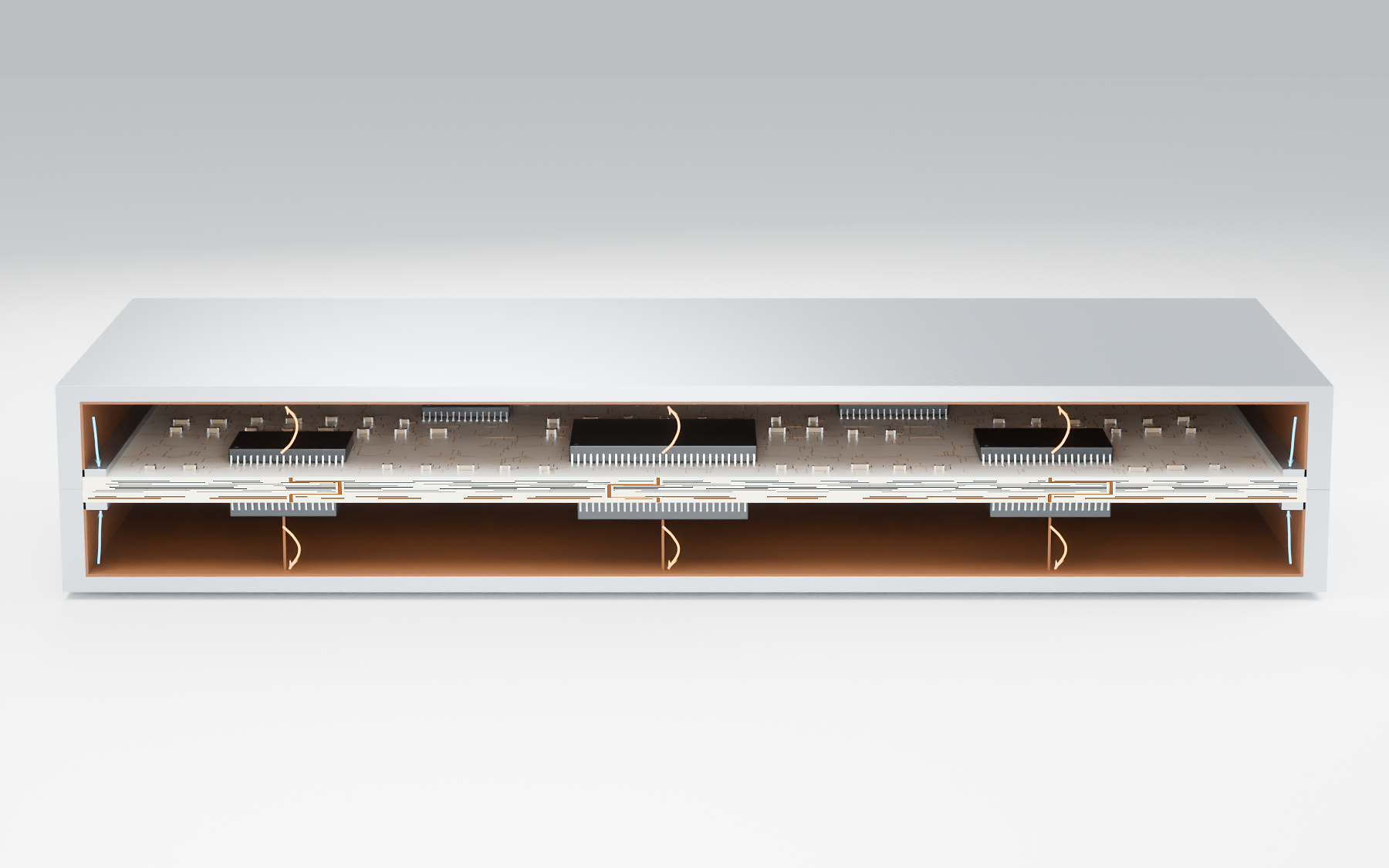
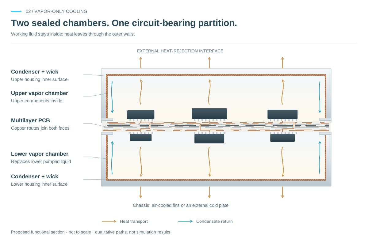
The single-sided concept places the vapor chamber below the PCB. Top-side components and antenna areas remain exposed to the environment; selected thermal paths carry heat to the underside evaporator interface. The double-sided concept encloses components on both faces in separately sealed chambers. Each chamber has its own working-fluid charge, vapor space, condenser surface and wick return path.
Heat passes through the condenser housing to the product’s heat-rejection system. Both versions have no pumped liquid passage through the module. “Vapor only” still includes a sealed liquid working fluid that evaporates and condenses.
Switches every 3 seconds · Select a tab to hold a view.
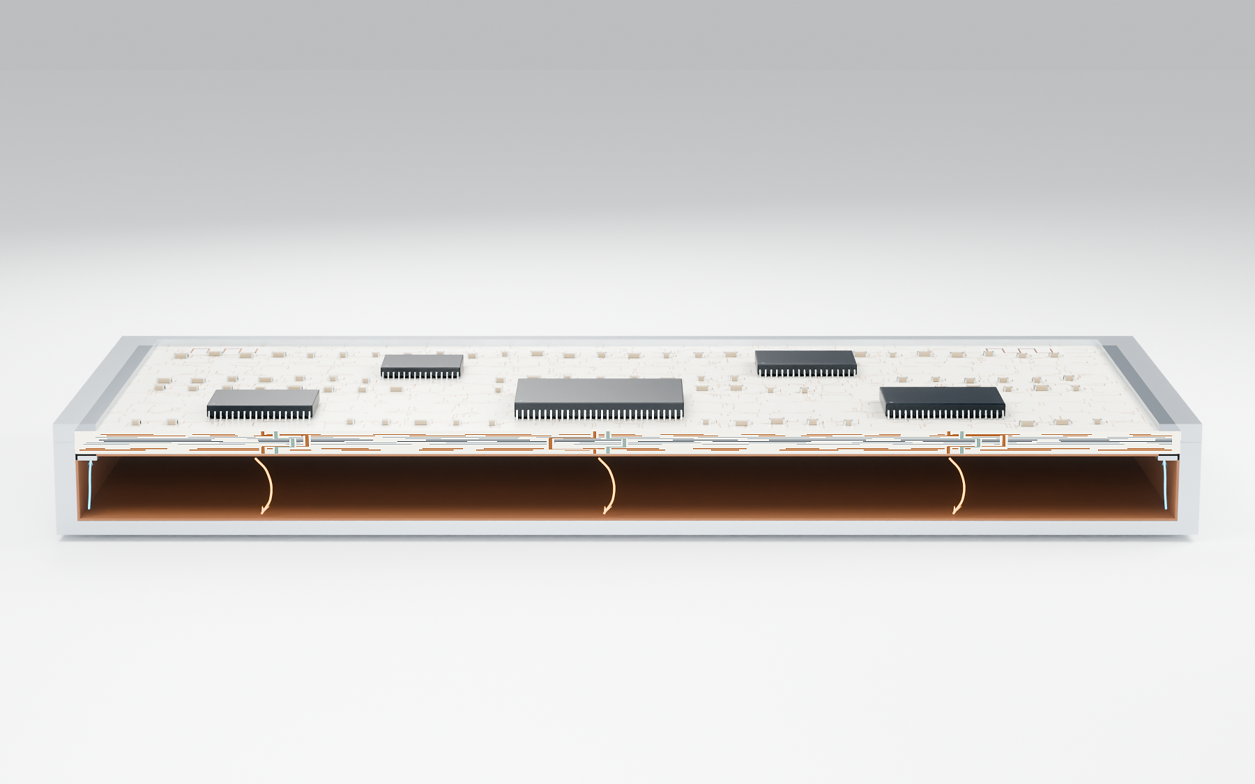
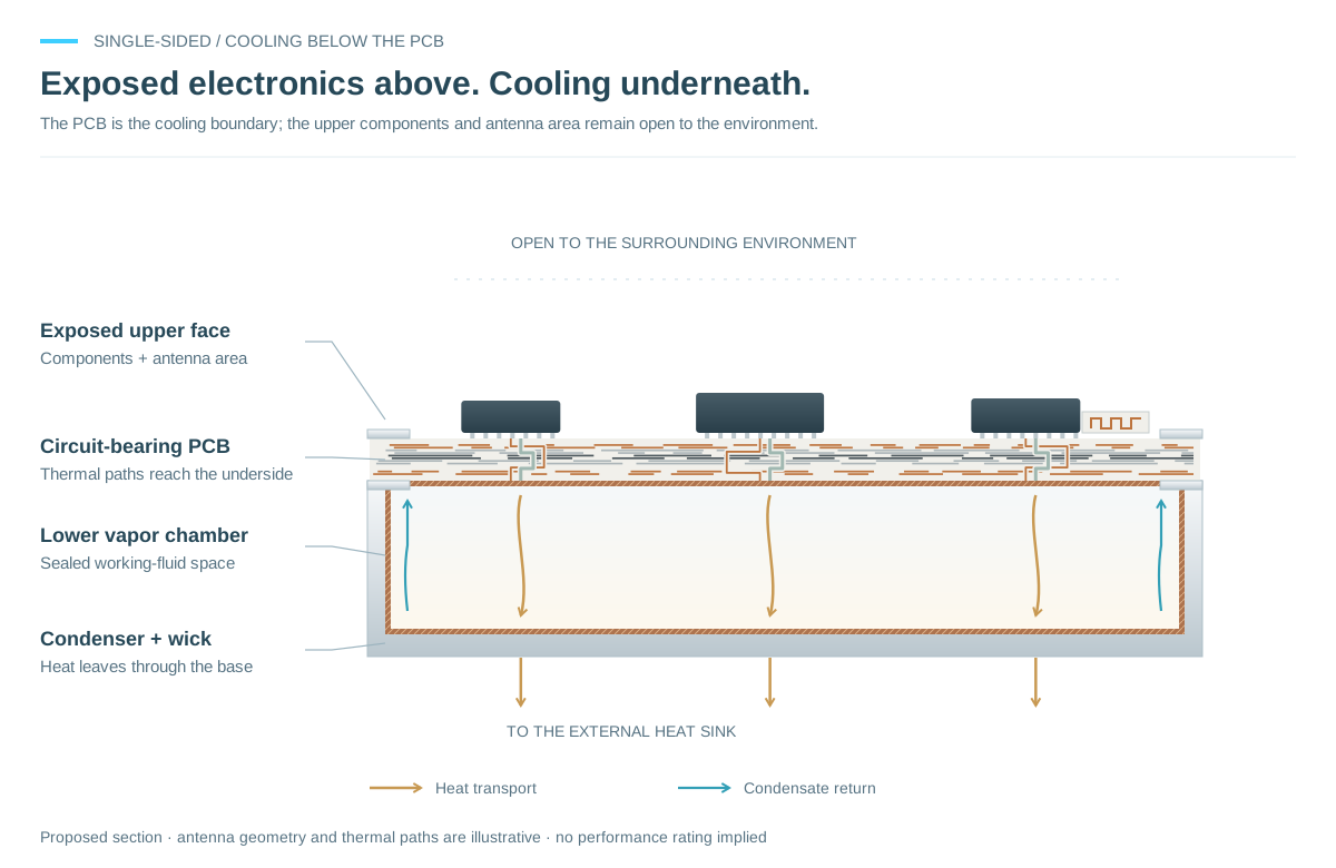
Place the cooling chamber below the PCB and leave the upper electronics, antenna area and interfaces exposed. Design thermal transfer through the board together with RF clearances and environmental requirements.
Place a sealed chamber on each populated face. Define the fluid inventory, vapor clearance and return path for each chamber independently.
Couple condenser walls to a chassis, air-cooled fins or an external liquid cold plate. A vapor chamber transports and spreads heat; the complete product still needs a path to reject it.
Fluid and electrical compatibility, a continuous liquid supply to heated surfaces, wick performance in the intended orientation, pressure containment, hermetic feedthroughs, board deflection, thermal cycling and external heat rejection must be designed together. The illustrations show possible configurations, not validated products or rated performance.
General two-phase background: evaporation, condensation and wick return. The board-integrated arrangements shown here are proposed ColdBoard concepts.
03 / LIQUID-COOLED VAPOR CHAMBER
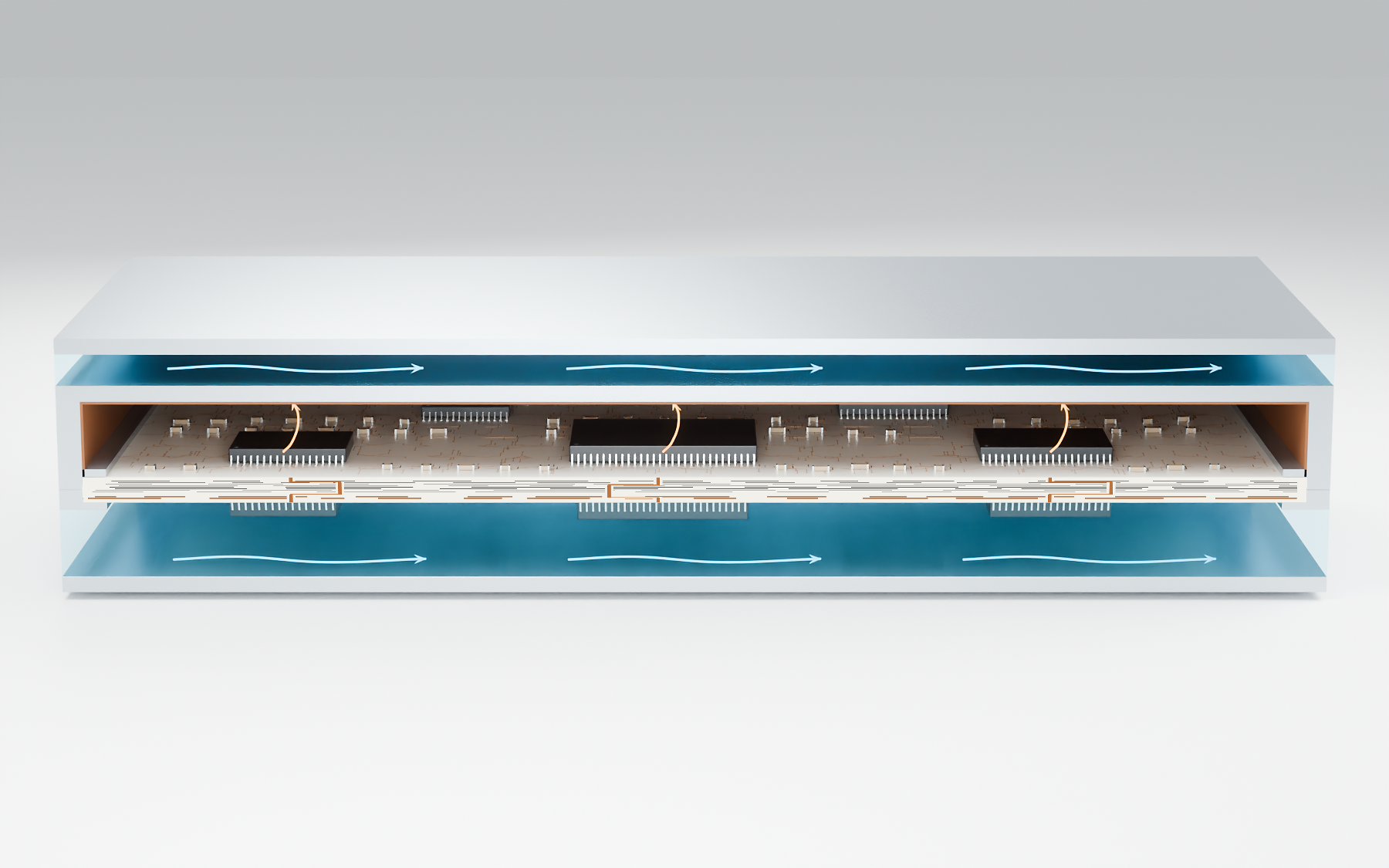
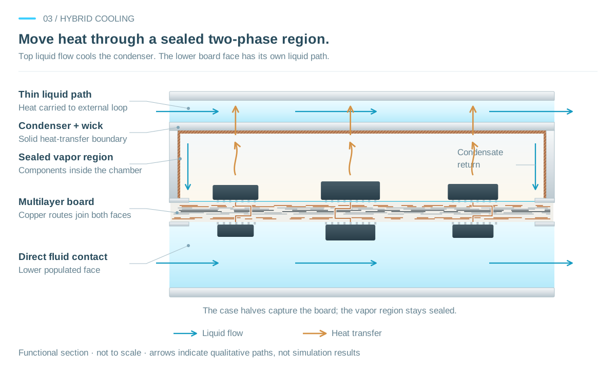
The board itself forms the sealed lower wall of the vapor chamber.
The upper electronics share a sealed working-fluid region. Heat from wetted component surfaces travels through evaporation and condensation to the chamber’s roof. A thin liquid chamber above that solid roof carries the heat away; condensate returns to the heated region. The lower populated face has its own pumped dielectric cooling. Both liquid chambers connect through wide rectangular openings at their opposing short ends.
Select compatible electrical and phase-change properties for the intended temperature range.
Define how condensed fluid reaches heated surfaces under the intended operating orientation.
The top liquid flow removes heat at the condenser wall and carries it to an external heat-rejection loop. Flow distribution, temperatures and condensate return require analysis and testing.
PRODUCT DIRECTIONS FOR LICENSEES
Start with the product envelope, device layout and available heat sink. These are illustrative directions a licensee could evaluate.
A one- or two-sided vapor arrangement could spread heat to external fins, with natural or forced airflow selected for the actual load and environment.
Use sealed chambers and board-integrated thermal paths to transfer heat toward enclosure interfaces while preserving the required electrical isolation.
Pair vapor chambers with external cold plates, or evaluate direct liquid and hybrid boundaries where a cooling loop is already part of the platform.
The separate blade concept explores a replaceable enclosure with distributed dielectric flow. Other chamber choices would require a new module and interface design.
View the blade conceptEVALUATION & LICENSING
Compare the chamber arrangement, external heat sink and product envelope in a focused licensing evaluation.