Internal thermal termination
Collect heat at an internal layer rather than requiring every path to span the full substrate. Review lateral spreading, layer interfaces and electrical clearance together.
Technology
ColdBoard describes ways to incorporate thermal transport into the circuit-bearing structure, alongside the electrical and mechanical functions it must perform.
01 / COLLECT AND ROUTE
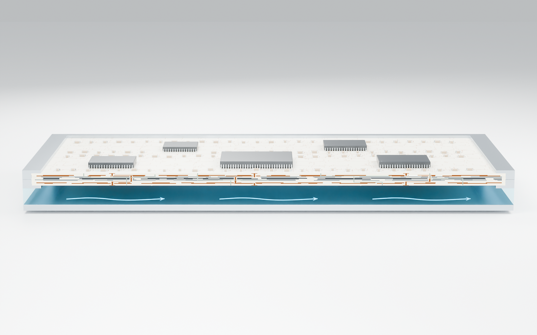
Surface-mounted or embedded devices can couple to localized thermally conductive, electrically insulating regions. These regions can connect through selected layers or laterally toward an internal distribution structure.
The thermal route need not follow the electrical route or pass through the full board thickness. Layer placement and material selection depend on the device, isolation requirements and cooling boundary.
02 / CONNECT TO THE SYSTEM
The cooling region can sit beside the circuit-bearing structure.
A separate opposing wall can complete a coolant region while the board forms another boundary. Thermal distribution layers and protective interfaces can participate in transferring heat to that region.
Internal channels are one possible implementation. Other arrangements use liquid, sealed working-fluid regions, solid conduction or a housing interface.
See the section diagrams03 / DESIGN CHOICES
Collect heat at an internal layer rather than requiring every path to span the full substrate. Review lateral spreading, layer interfaces and electrical clearance together.
Route heat toward an appropriate thermal structure while conductors route power and signals elsewhere. Assembly, inspection and repair remain part of the design.
Evaluate a chamber on one or both board faces, or combine a vapor region with direct liquid cooling. Each sealed chamber needs an evaporator, condenser, liquid return path and external heat sink designed as a complete system.
Explore vapor-only optionsThe public disclosure includes non-planar and flexible structures and thermal coupling to a housing or chassis. The physical implementation follows the application.
Source: published Thermal PCB description, including Figures 1–4 and 6–9. Read at WIPO.
A SHORT TECHNICAL GLOSSARY
The substrate or structural member that supports circuitry and electrical interconnections. It can also take part in thermal transport or form a cooling boundary.
An electrically insulating material selected to carry heat. Its electrical, thermal and mechanical properties must suit the intended duty.
Connected regions that collect, redirect or spread heat before it reaches a cooling interface. A functional network does not imply one universal material or geometry.
A thermal interface that incorporates protection or isolation appropriate to the adjacent fluid and materials. Its composition and thickness affect thermal resistance.
EVALUATION & LICENSING
Then define the path, electrical isolation and cooling boundary together.